How to Select an Industrial Gearbox: Ratio, Service Factor & Mounting

A motor running hotter than it should. A gearbox that seizes six months after commissioning. A conveyor that stalls the moment the load reaches full capacity. Nine times out of ten, a plant calls us in to investigate a failure like this. The root cause traces back to one decision made months earlier. How to select a gearbox for that specific duty was never worked out properly in the first place.
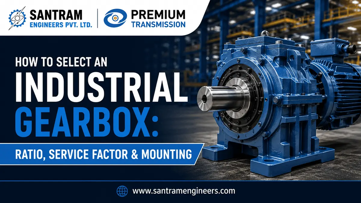
To select a gearbox correctly, match four things: output speed via gear ratio, load after service factor, gearbox type for the duty, and a mounting setup that keeps lubrication and shaft alignment correct. Skip any one of these and a routine purchase turns into a recurring maintenance problem.
Gearbox failure is rarely about the gear teeth themselves. It’s almost always a mismatch between paper specifications and how the machine runs on the shop floor. Shock loads and ambient heat nobody accounted for do the real damage. We’ve sized reduction drives for cement plants, sugar mills and material handling systems across India for four decades. The method below is what our engineers walk through before recommending any unit.
The 5 Inputs You Need Before You Size a Gearbox
You cannot select a gearbox from a part number alone. A supplier who quotes you a unit without asking about your application is guessing, not engineering. Before any sizing calculation happens, gather these five inputs.
Input Power and Speed
What is actually driving the gearbox? Usually an electric motor, so note its rated kW and RPM. In India, this is almost always a 4-pole motor running at roughly 1440 RPM on a 50Hz supply. That detail matters more than it sounds. Most international sizing charts default to 60Hz, 1750 RPM motor speeds. Copy one without adjusting, and it will quietly hand you the wrong ratio.
Required Output Speed
What speed does the driven machine actually need? A conveyor pulley, a mixer shaft, a bucket elevator — each has a target output RPM. That number comes from the process, not from whatever the gearbox catalogue happens to offer.
The Ratio
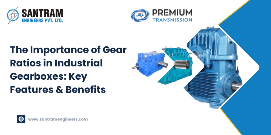
Divide input speed by output speed to get your required reduction. If your motor runs at 1440 RPM and the driven shaft needs 48 RPM, you need a 30:1 ratio. Gearboxes are built in standard ratio steps. Once you calculate the exact figure, pick the closest standard ratio that meets your speed target without pushing torque past the unit’s rated limit. Getting the gear ratio calculation right from the start is what everything else in this guide builds on.
Duty Cycle
How hard, and how often, does the drive run? Eight hours a day of smooth, uniform load is a different application from 24-hour operation with shock loads and frequent starts. This single factor decides your service factor, which is the next section.
Environment
Ambient temperature, dust, moisture, hazardous atmosphere and available mounting space all change the selection. A gearbox in an air-conditioned packaging hall and one standing next to a cement kiln at 50°C ambient are not the same selection, even at identical torque. Indian summers regularly push shop-floor temperatures near kiln and boiler sections well past what a European or North American chart assumes as “normal.” Thermal derating deserves a real second look here, not a one-line footnote.
Understanding Service Factor and Why It Decides Gearbox Life
Service factor is the multiplier that separates a gearbox rated on paper from a gearbox that survives real operating conditions. It accounts for shock loads, frequent starts and stops, long running hours, and the nature of the driven machine. None of that shows up in a basic kW-to-kW comparison.
How the Calculation Works
Suppose your application needs 5 kW of output power. The driven machine is a screw conveyor running 24 hours a day with moderate shock, which calls for a service factor of about 1.5. You do not select a 5 kW gearbox. You select one rated for at least 5 x 1.5 = 7.5 kW of mechanical capacity at your target ratio. That headroom absorbs real-world stress instead of quietly eating into the gear teeth’s fatigue life every time the load spikes.
Why Most Industrial Duties Fall Between 1.3 and 1.7
Uniform, low-shock loads running a few hours a day can sit closer to a service factor of 1.0-1.25. A crusher, mixer or shredder running continuously with heavy shock loading often needs 1.75 to 2.0 or higher. Most general industrial conveying and material handling duty in Indian plants falls in the 1.3 to 1.7 band. That range assumes AGMA-style ratings, though, and this is where confusion creeps in for buyers comparing imported and domestically manufactured units.
AGMA, ISO and Why the Same Number Isn’t the Same Gearbox
AGMA-based service factor and ISO 6336’s application factor (Ka) serve the same purpose. But they come from different rating methodologies. ISO-derived ratings typically produce higher torque and power figures than AGMA for a physically identical gear. Two catalogue entries showing an identical torque rating — one AGMA-referenced, one ISO-referenced — are not necessarily equivalent in practice. Bearing life assumptions compound this further. Commercial-grade units are commonly rated to an L10 bearing life of around 5,000 hours. Industrial-grade gearboxes target roughly 100,000 hours instead. A service factor of 1.5 on a commercial-rated unit gives far less real margin than the same 1.5 on a properly industrial-rated one. When comparing quotations from different manufacturers or import sources, ask which standard the service factor references. The number alone doesn’t tell the full story.
| Duty Type | Typical Running Hours | Recommended Service Factor |
|---|---|---|
| Light, uniform load (packaging, light conveying) | Up to 8 hrs/day | 1.0 – 1.25 |
| Moderate shock (general conveyors, mixers) | 8 – 16 hrs/day | 1.3 – 1.6 |
| Continuous, heavy shock (crushers, shredders, kilns) | 24 hrs/day | 1.75 – 2.0+ |
Treat any of these figures as a starting point, not a substitute for checking the manufacturer’s own application tables. Actual values shift by gearbox type and torque class.
Choosing the Gearbox Type: Worm, Helical or Planetary
Once ratio and service factor are settled, gearbox type comes down to efficiency, footprint, ratio range and how much shock the drive absorbs.
Worm Gearboxes
Worm units deliver high ratios in a compact right-angle package. They run quietly, and some configurations offer self-locking behaviour that resists back-driving. The trade-off is lower efficiency and more heat at high ratios. That matters more in continuous-duty applications than intermittent ones. They suit many material handling, mixing and lifting duties well.
Helical and Bevel-Helical Gearboxes
Helical designs run at higher efficiency than worm units and handle continuous duty and higher power better too. Energy cost over the gearbox’s lifetime usually matters more than upfront price, especially for anything running more than one shift a day. In that case, helical or bevel-helical is the default choice.
Planetary Gearboxes
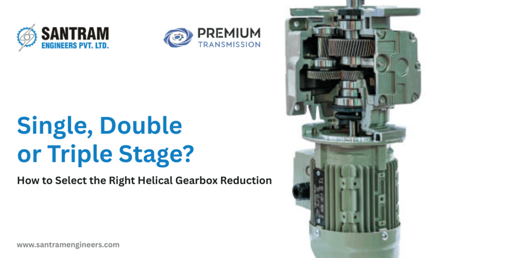
Planetary units pack the highest torque density into the smallest footprint of the three. They suit high-torque, high-shock or space-constrained drives, where a worm or helical unit of equivalent capacity simply would not fit.
| Type | Typical Ratio Range | Efficiency | Best Suited For |
|---|---|---|---|
| Worm | 5:1 to 100:1+ | Moderate (60-90%, drops at high ratio) | Compact right-angle drives, mixers, lifting |
| Helical / Bevel-Helical | 5:1 to 60:1 (per stage, higher with multi-stage) | High (94-98%) | Continuous duty, conveyors, energy-sensitive lines |
| Planetary | 3:1 to 500:1+ (multi-stage) | High (95-98%) | High-torque, high-shock, space-constrained drives |
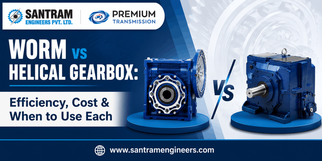
Our guide on how each of these gearbox types performs across different industrial applications goes deeper into weighing them against your actual duty cycle, rather than defaulting to whatever your plant has always used. Never pick the type before torque, ratio and duty are nailed down. Type selection is the third decision, not the first.
Mounting Position and Shaft Configuration Mistakes to Avoid
Mounting position is where a correctly sized gearbox still fails. Lubrication and mounting orientation are linked in ways that are easy to overlook on a drawing.
Match Lubrication to Actual Orientation
A horizontal-foot-mounted unit will not lubricate correctly if it ends up mounted vertically or on an incline. The oil quantity and breather position both need adjusting for that angle. A gearbox that takes a given oil fill flat on a foot mount may need a different fill level at even a 15-20 degree incline, plus a relocated breather. Raise the actual installation angle with your supplier before the unit ships. Don’t wait until commissioning, when the wrong fill is already inside the housing.
Match Shaft Configuration to the Driven Machine
Solid versus hollow shaft, diameter, keyway profile, and flange-mount versus foot-mount all need to match the driven machine’s interface exactly. A hollow-shaft unit ordered against a solid-shaft drawing turns a routine delivery into a rework job on-site.
Common Sizing Mistakes We See Repeated
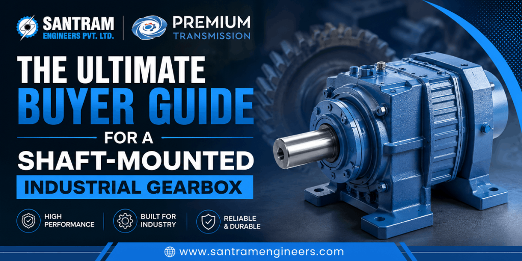
Five mistakes account for most of the premature failures we investigate. Ignoring service factor entirely. Sizing to motor nameplate power instead of the actual driven load. Choosing the wrong mounting orientation for the installed position. Overlooking thermal derating in high-ambient environments. And mismatching the shaft or flange interface. Every one of these is avoidable once the five inputs from the first section are actually gathered before ordering. Our installation guide for industrial gearboxes covers how mounting errors typically surface during commissioning.
Worked Example: Sizing a Gearbox for a Belt Conveyor
Here is how these pieces come together on an actual specification, the way our application engineers approach it.
The belt pulley needs to run at roughly 48 RPM. The motor is 5.5 kW, 4-pole, 1440 RPM — standard for an Indian plant on a 50Hz supply. That gives a ratio of 1440 / 48, which works out to 30:1. Duty is 16 hours a day with moderate shock, putting the service factor at roughly 1.4. Required mechanical capacity becomes 5.5 x 1.4, or about 7.7 kW at 30:1. The installation site has a dusty floor and normal ambient temperature, so there’s no extreme heat to derate for.
The resulting selection is a helical or bevel-helical geared motor rated comfortably above 7.7 kW at 30:1. It needs a foot or flange mount matching the existing frame, with a solid output shaft sized to the pulley bore. The “30:1, 5.5 kW” starting point on the motor nameplate was only the opening line of the specification. Service factor, duty cycle, mounting and dust environment turned it into a real, buildable spec. This same logic applies whether you’re sizing a single pulley or an entire line. Our detailed breakdown of gearbox selection for conveyor systems walks through several conveyor-specific variations on this same example.
When to Get an Application-Engineering Sizing Check
Some situations are worth a second set of eyes before you place the order. High-shock duties like crushers or shredders. Inclined or unusual mounting positions. Hazardous or high-temperature environments. Energy-critical continuous operation, where efficiency losses compound over years. And constrained retrofits, where the new unit has to fit an old footprint. A sizing review in these cases costs a phone call. Getting it wrong costs a replacement gearbox and the downtime that comes with it.
It’s worth being honest about one limitation here. No sizing guide, including this one, replaces checking your final selection against the manufacturer’s own service factor tables and thermal rating charts for that model. General guidance gets you to the right ballpark. The manufacturer’s data sheet confirms the exact unit.
Frequently Asked Questions
How do I calculate the gear ratio I need for my application?
Divide your motor’s input RPM by the output RPM your driven machine actually requires. A 1440 RPM motor driving a shaft that needs 48 RPM requires a 30:1 ratio. Once you have the exact figure, select the closest standard ratio your chosen gearbox range offers.
What service factor should I use for a conveyor running 24 hours a day?
Most continuous-duty conveyors with moderate shock sit in the 1.4 to 1.6 range. Heavier shock loading from lumpy or variable material pushes this toward 1.75 or higher. Always check the actual application table for your specific gearbox type, rather than applying a single number across every duty.
Can a horizontal foot-mounted gearbox be installed vertically without changes?
No. Mounting orientation changes how the internal components sit in the oil. A unit filled and vented for a horizontal mount will not lubricate correctly at a vertical or inclined angle without an adjusted oil quantity and breather position. Confirm the actual installation angle with your supplier before the unit is filled and shipped.
Is a planetary or helical gearbox better for high-shock applications?
Planetary gearboxes generally handle high-shock, high-torque duty better within a smaller footprint. Helical units are the stronger choice for continuous, steady-load operation, where efficiency matters more than shock absorption. The right answer depends on which of those two conditions dominates your actual duty cycle.
Why does India’s 50Hz motor speed matter for gearbox selection?
Indian plants typically run 4-pole motors at around 1440 RPM on a 50Hz supply. Many international sizing charts and catalogues are built around 60Hz, 1750 RPM motor speeds instead. Applying an imported ratio chart without adjusting for this produces an output speed that doesn’t match what your process actually needs.
What happens if I size a gearbox using motor power instead of actual load?
Motor nameplate power reflects what the motor can deliver, not what the driven machine actually demands once service factor and duty cycle are applied. Sizing to motor power alone is one of the most common causes of premature gearbox failure. It skips the safety margin that absorbs real-world shock and starting loads.
Get Your Gearbox Sizing Verified Before You Order
Knowing how to select a gearbox comes down to the same four checks every time: ratio, service factor, type and mounting, worked out in that order before you touch a catalogue. Getting all four right on paper is most of the job. But every application has a detail a general guide can’t fully account for, whether that’s an unusual incline, a hazardous zone, or an oddly constrained retrofit space. Santram Engineers has been sizing and supplying gearboxes for cement plants, sugar mills, steel lines and material handling systems across India for over four decades, with PAN India shipping on every order. If you’re finalising a specification and want a second check before committing to a purchase order, request a sizing check from our application engineering team. We’ll review your ratio, torque and duty inputs against the actual gearbox model before you order.