
How to Select the Right Helical Geared Motor for an Agitator: A Torque Calculation Guide

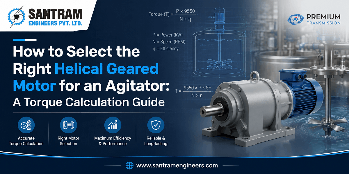
Undersizing an agitator drive shows up almost immediately — the motor trips on start-up, the gearbox overheats within weeks, or the mix simply never reaches the consistency the process needs. Oversizing is quieter but just as costly: you pay for capacity you never use, and the extra torque puts unnecessary stress on the shaft and seals. The difference between the two almost always comes down to one step most buyers skip — calculating actual torque instead of guessing horsepower from a catalogue.
A helical geared motor is the standard choice for agitators because it delivers high torque at low output speed in a compact, coaxial package — exactly what a mixing application needs. But selecting the right one is not a matter of picking a motor rating and matching it to a gearbox ratio. Our broader geared motor selection guide covers general sizing principles across conveyors, mixers, crushers, and lifting systems — this guide goes deeper specifically for agitators, working through the fluid properties, impeller geometry, and starting conditions first, then sizing the drive around the torque those conditions actually demand.
This guide walks through that calculation step by step, with a full worked example, so you can size an agitator drive with numbers instead of assumptions.
Quick answer: Agitator torque is derived from the power required to turn the impeller (P = Np × ρ × N³ × D⁵), converted to torque using T = 9550 × P ÷ N. Add a margin for starting torque under settled or viscous conditions, then apply a service factor for continuous duty before selecting your gearbox’s rated output torque.
What You Need Before You Start Sizing an Agitator Drive
Before any calculation, gather these parameters. Skipping any one of them is the most common reason agitator drives are undersized in the field.
| Parameter | Why It Matters |
|---|---|
| Fluid density (ρ) | Directly scales power requirement |
| Fluid viscosity | Determines flow regime (laminar/turbulent) and affects the power number |
| Impeller type and diameter (D) | Sets the power number and dominates the power equation — power scales with D⁵ |
| Agitator speed (N) | Power scales with the cube of speed — small speed changes matter a lot |
| Tank diameter and geometry | Affects flow pattern, baffling, and impeller-to-tank ratio |
| Solids content / settling behaviour | Determines starting (breakaway) torque requirement |
| Duty cycle | Continuous 24/7 operation needs a higher service factor than intermittent use |
Step 1: Understand Your Fluid Properties
Density and viscosity are the starting point for every calculation that follows. For Newtonian fluids — water-based mixes, most dilute solutions — viscosity stays constant regardless of shear rate, which keeps the calculation straightforward. Non-Newtonian fluids, common in paints, slurries, food batters, and polymer solutions, behave differently: their apparent viscosity changes with shear rate, and many exhibit a yield stress that must be overcome before the fluid moves at all. This second category is exactly where agitator drives most often get undersized, because the running torque looks manageable on paper while the starting torque, calculated separately, turns out to be several times higher.
Step 2: Choose Your Impeller Type and Find Its Power Number
The power number (Np) is a dimensionless value specific to each impeller geometry, determined experimentally under turbulent flow conditions. It tells you how much power a given impeller draws per unit of speed and diameter.
| Impeller Type | Typical Power Number (Np) | Common Use |
|---|---|---|
| Rushton (flat-blade) turbine | ~5.5 | Gas dispersion, high-shear blending |
| 45° pitched-blade turbine | ~1.27 | General-purpose blending, solids suspension |
| Anchor | ~0.35 | High-viscosity, low-shear mixing near tank walls |
| Helical ribbon | Variable, geometry-dependent | Very high-viscosity, laminar-flow mixing |
Choose the impeller based on your process need — blending, solids suspension, gas dispersion, or heat transfer — before moving to the power calculation, since the wrong impeller choice makes every downstream number irrelevant.
Step 3: Calculate the Power Requirement
With the fluid properties and impeller selected, the theoretical power draw at the impeller is:
P = Np × ρ × N³ × D⁵
Where P is power in watts (using SI units throughout), Np is the power number, ρ is fluid density in kg/m³, N is agitator speed in revolutions per second, and D is impeller diameter in metres.
Two things stand out in this formula. First, power scales with the fifth power of impeller diameter — doubling the impeller diameter increases power demand by a factor of 32, not two. Second, power scales with the cube of speed, so a seemingly small increase in RPM during process trials can push your drive well past its rated capacity. Both are reasons to lock in your final process speed and impeller diameter before finalizing the drive, not after.
Step 4: Convert Power to Torque — the Number That Actually Sizes Your Gearbox
Horsepower or kilowatt rating alone does not size a gearbox — torque does. Two motors with identical power ratings but different output speeds will need very differently rated gearboxes, because torque and speed are inversely related for a fixed power. Convert calculated power to torque using:
T (Nm) = 9550 × P (kW) ÷ N (rpm)
This torque figure — not the motor’s HP rating — is what you match against the gearbox manufacturer’s rated output torque at your target speed.
Step 5: Add a Margin for Starting (Breakaway) Torque
Running torque and starting torque are not the same number, and this is where undersized drives most often fail in the first week of operation. If the tank has been sitting idle, settled solids can require significantly more torque to break loose than the impeller needs once the fluid is moving. Non-Newtonian fluids with a yield stress behave the same way — the drive has to overcome that yield stress before flow even begins. As a working rule, budget 20-40% above running torque for the starting condition, with the higher end reserved for tanks that regularly sit with settled solids or high-yield-stress products.
Step 6: Apply Service Factor Before Finalizing Gearbox Size
Once you have a torque figure that accounts for starting conditions, apply a service factor before selecting the actual gearbox model. Continuous 24/7 duty, shock loading from batch charging, or operation in high-ambient-temperature plants all justify a higher factor. As a general guide, continuous-duty agitators are typically sized with a service factor of 1.5, and applications with frequent starts, high-solids content, or shock loading often warrant 1.75-2.0. This is not a figure to estimate loosely — check it against the gearbox manufacturer’s rating tables for your specific duty class, since running a gearbox below its intended service factor is the single most common cause of premature bearing and gear failure in agitator drives.
Step 7: Choose the Right Mounting Configuration
Mounting configuration affects more than installation convenience — it determines how axial thrust from the impeller is handled. Top-entry agitators, the most common configuration for tank mixing, load the gearbox output shaft with continuous axial thrust from the impeller pushing against the fluid. A vertical hollow-shaft helical geared motor with an integral thrust bearing is built to carry this load directly. Foot-mounted horizontal units connected through a flexible coupling are common on side-entry or angled installations, where the thrust load is lower or handled separately. Getting this wrong — using a standard foot-mounted unit without adequate thrust capacity on a top-entry application — is a frequent cause of premature bearing wear, even when the torque and power calculations were done correctly.
Worked Example: Sizing a Geared Motor for a 5,000-Litre Mixing Tank
Take a stainless steel tank holding a 5,000-litre batch of a near-water-viscosity chemical blend, using a top-entry 45° pitched-blade turbine.
- Impeller power number, Np = 1.27
- Fluid density, ρ = 1,000 kg/m³
- Agitator speed, N = 90 rpm (1.5 rev/s)
- Impeller diameter, D = 0.7 m
Step 1 — Power: P = 1.27 × 1,000 × (1.5)³ × (0.7)⁵ = approximately 720 W, or 0.72 kW.
Step 2 — Add mechanical loss and process margin: Adding roughly 10% for transmission losses and 25% process margin brings this to approximately 1.0 kW. Rounding up to the nearest standard rating gives a 1.1 kW (1.5 HP) motor.
Step 3 — Torque at output speed: T = 9550 × 1.1 ÷ 90 ≈ 117 Nm.
Step 4 — Apply service factor: For continuous-duty operation, applying a 1.5 service factor gives a required gearbox rated output torque of approximately 175 Nm at 90 rpm.
Result: The selection target is a helical geared motor rated for at least 175 Nm output torque at 90 rpm, in a vertical hollow-shaft configuration with an integral thrust bearing to handle the top-entry impeller load.
Common Sizing Mistakes to Avoid
- Sizing on horsepower alone, without converting to torque at the actual output speed
- Ignoring starting torque for tanks that sit idle with settled solids
- Using a foot-mounted unit on a top-entry application without adequate thrust bearing capacity — see our shaft-mounted industrial gearbox guide for more on matching mounting style to load type
- Applying an insufficient service factor for continuous 24/7 duty
- Finalizing impeller diameter after motor selection instead of before — since power scales with D⁵, a late diameter change invalidates the entire calculation
Frequently Asked Questions
How do I calculate torque for an agitator?
First calculate the theoretical power using P = Np × ρ × N³ × D⁵, then convert to torque using T (Nm) = 9550 × P (kW) ÷ N (rpm). Add a margin for starting torque, then apply a service factor for your duty cycle before finalizing the gearbox selection.
What HP motor do I need for an agitator tank?
It depends entirely on fluid density, viscosity, impeller diameter, and target speed — there is no fixed HP-per-litre rule. A 5,000-litre tank with a low-viscosity fluid may need under 2 HP, while a smaller tank with a high-viscosity, high-solids mix can require significantly more. Always calculate from the actual process parameters.
What is the difference between an agitator motor and a general mixer motor?
An agitator drive is typically paired with a helical or planetary gearbox specifically sized for the torque and thrust conditions of the tank, often in a vertical hollow-shaft configuration with an integral thrust bearing. A general-purpose mixer motor may not account for axial thrust loading or the starting torque of settled/viscous process fluids.
How do I select the correct gearbox ratio for an agitator?
The ratio is determined by the target agitator speed relative to the motor’s base RPM. Once you know your required output torque and speed from the calculation above, select a gearbox model whose rated output torque at that specific output speed meets or exceeds your service-factor-adjusted requirement.
What service factor should I use for a continuous-duty agitator?
A service factor of 1.5 is a common starting point for continuous 24/7 operation with steady loads. Applications with frequent starts, high solids content, or shock loading from batch charging often require 1.75 to 2.0 — always confirm against the gearbox manufacturer’s duty class ratings for your specific application.
Why does impeller diameter matter so much in the power calculation?
Because power scales with the fifth power of impeller diameter (D⁵) in the standard power number equation. A relatively small increase in impeller diameter significantly increases the power — and therefore torque — the drive must deliver, which is why the impeller diameter should be finalized before selecting the motor and gearbox.
Getting the Selection Right the First Time
Agitator drive sizing has more moving parts than a simple HP lookup — fluid behaviour, impeller geometry, starting conditions, service factor, and mounting configuration all interact, and getting one wrong undermines the rest of the calculation. Working through the numbers in the order above, rather than starting from a catalogue rating, is what separates a drive that runs reliably for years from one that needs replacing within its first season.
At Santram Engineers, we supply helical geared motors, including vertical hollow-shaft configurations built for top-entry agitator applications, across food processing, pharmaceuticals, chemical, and material handling industries. If you have a specific tank size, fluid, and process requirement, our team can review the calculation with you and match it to the right gearbox and motor combination.
Call us at +91 96247 39393 or write to us to get your agitator drive sized and quoted.
