
Worm Gearbox Efficiency and Backlash Explained: The Role of Ratio and Thread Starts

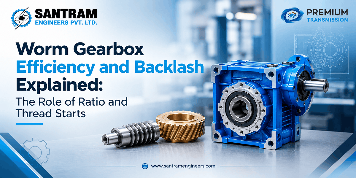
If you’ve ever spec’d a worm gearbox and found that it runs noticeably hotter than a helical unit, or noticed the output shaft moves a fraction of a degree before the load responds after a direction change — you’ve already encountered the two defining characteristics of worm gear drives: efficiency loss and backlash. Neither is a defect. Both are built into the geometry of how worm gears work, and understanding them determines whether a worm gearbox is the right choice for a given application.
This post breaks down worm gearbox efficiency from first principles — the formula, how it changes with gear ratio and number of thread starts, and what the self-locking zone means for drive design. It also explains worm gearbox backlash: what causes it, how it’s measured, and how to manage it.
What Is Worm Gearbox Efficiency?
Worm gearbox efficiency is the ratio of mechanical output power to electrical input power, expressed as a percentage. It ranges from roughly 35% at high ratios with a single thread start to above 90% at low ratios with four or more starts. The primary loss mechanism is sliding friction between the worm and the bronze wheel — not rolling contact, as in helical or bevel gears.
Efficiency is lower in worm drives than in most other gear types because the worm and wheel teeth slide across each other rather than rolling. Every millimetre of tooth engagement converts some input energy into heat instead of output torque. This is the fundamental trade-off you accept when choosing a worm gearbox: a compact, right-angle drive with high ratios in a single stage, at the cost of efficiency.
Compared to other gear types, the gap is significant. A double-reduction helical gearbox typically reaches 97–98% efficiency per stage. A bevel-helical unit sits at 95–98%. A worm gearbox at a 40:1 ratio with a single-start worm might deliver 52–65% efficiency — meaning up to 48% of motor input power becomes heat. For buyers deciding between a worm gearbox and a helical unit, this efficiency difference is often the deciding factor on any application running more than four to six hours a day.
The Efficiency Formula: Lead Angle, Friction Angle, and Worked Examples
Worm gearbox efficiency is governed by a straightforward mechanical relationship between two angles:
η = tan(λ) / tan(λ + φ)
Where:
— η is mechanical efficiency (as a decimal; multiply by 100 for percentage)
— λ (lambda) is the lead angle of the worm thread
— φ (phi) is the friction angle, equal to arctan of the coefficient of friction between the worm and wheel
The lead angle is the helix angle at the pitch diameter — essentially the inclination of the thread as it wraps around the worm shaft. A steeper lead angle means the thread advances more per revolution, which produces less sliding per unit of tooth engagement. A larger lead angle always means higher efficiency.
The friction angle captures how much resistance exists at the contact surface. A hardened steel worm running against a phosphor-bronze or tin-bronze wheel, properly lubricated, produces a coefficient of friction in the range of 0.03 to 0.08 at operating temperature. A dry or poorly lubricated contact can push this to 0.15 or higher — which directly drives down efficiency, and is why lubricant condition is one of the most important variables in actual installed performance.
Worked example 1: Lead angle λ = 5°, friction angle φ = 6° (coefficient of friction ≈ 0.105):
η = tan(5°) / tan(5° + 6°) = 0.0875 / 0.1944 ≈ 45%
Worked example 2: Same worm with λ = 15° and φ = 5°:
η = tan(15°) / tan(15° + 5°) = 0.268 / 0.364 ≈ 74%
The 29-percentage-point difference between these two examples comes purely from the change in lead angle. This is why the number of thread starts — which is what sets the lead angle for a given ratio — matters so much in drive selection.
How Thread Starts Control Efficiency
The number of thread starts directly determines the lead angle for a given gear ratio. A single-start worm with a 40-tooth wheel produces a 40:1 ratio. A two-start worm with the same 40-tooth wheel produces a 20:1 ratio — and for the same axial pitch, the lead angle roughly doubles.
This relationship explains the efficiency table:
| Number of Starts | Typical Ratio Range | Typical Lead Angle | Efficiency Range | Self-Locking? |
|---|---|---|---|---|
| 1-start | 30:1 to 100:1 | 2°–5° | 40%–50% | Yes (reliable) |
| 2-start | 10:1 to 30:1 | 5°–10° | 70%–78% | Borderline |
| 3-start | 7:1 to 20:1 | 8°–15° | 75%–88% | No |
| 4-start | 5:1 to 15:1 | 10°–20° | 78%–92% | No |
A single-start worm achieves a high ratio in one stage — useful for low-speed, high-torque drives — but pays for it with a very shallow lead angle and correspondingly high sliding friction. A four-start worm achieves a moderate ratio with a much steeper lead angle, approaching the efficiency of a helical unit for low ratios.
For applications that don’t require self-locking and can accept a lower ratio per stage, specifying a two-start or four-start worm gearbox recovers significant efficiency. The difference between a 1-start 20:1 gearbox and a 2-start 20:1 gearbox can be 20–25 percentage points of efficiency on the same ratio — meaning a meaningful reduction in motor size, energy cost, and heat generation over the operating life.
Understanding how different thread-start configurations change drive behaviour is discussed in detail in our post on the difference between a single-start and two-start worm gearbox.
Worm Gearbox Efficiency by Gear Ratio — Reference Table
The following efficiency ranges reflect typical values for standard worm gearboxes with steel worm and bronze wheel, running with appropriate mineral or synthetic lubricant at normal operating temperature. Actual values depend on the number of starts for that ratio, lubricant quality, load level, and surface finish.
| Gear Ratio | Typical Efficiency | Practical Notes |
|---|---|---|
| 5:1 | 85–90% | Multi-start worm, approaching helical efficiency |
| 7.5:1 | 82–88% | Suitable for moderate-speed conveyors and agitators |
| 10:1 | 78–85% | Common in packaging lines, feeders |
| 15:1 | 73–82% | Transition zone between 2-start and 1-start designs |
| 20:1 | 68–78% | Efficiency depends heavily on lubrication quality |
| 25:1 | 62–75% | Heat dissipation begins to matter at this range |
| 30:1 | 58–72% | Nearly all single-start at this ratio |
| 40:1 | 52–65% | Continuous-duty applications should verify thermal power rating, not just mechanical torque rating |
| 50:1 | 48–62% | Below 50% efficiency is common; self-locking at lower end |
| 60:1 | 42–58% | Significant heat generation in continuous duty |
| 80:1 and above | 35–52% | Self-locking assured; motor sizing must account for losses |
A point the table makes clear: at ratios above 50:1, you are often rejecting nearly half the motor’s input power as heat. In continuous-duty applications — material handling, mixers, conveyors running six to eight hours a day — this has a direct energy cost and may require a larger gearbox frame to maintain safe oil temperatures.
One important distinction at ratios of 40:1 and above: a gearbox’s thermal power rating is typically lower than its mechanical torque rating. The mechanical rating tells you the maximum load the teeth and shafts can handle. The thermal rating tells you how much power the unit can continuously dissipate without the oil temperature exceeding safe limits. For continuous high-ratio drives, check the thermal rating from the manufacturer’s datasheet — specifying on mechanical torque alone can result in a unit that runs excessively hot even within its load limits. This is a common oversight in initial drive selection and often only surfaces after installation.
The Self-Locking Zone: When Efficiency Falls Below 50%
There is a mechanical threshold that deserves its own discussion. When efficiency falls below 50% — which corresponds to a lead angle smaller than the friction angle — a worm gearbox becomes self-locking. The wheel cannot drive the worm in reverse, even if the load applies significant torque to the output shaft.
This is not a failure mode. For vertical load-holding applications — screw jacks, valve actuators, lift tables, and similar machinery — self-locking is the design intent. The gearbox holds the load without a brake once power is removed.
However, self-locking also means that approximately half or more of the energy going in is being dissipated as friction. A truly self-locking gearbox with a lead angle of 4–5° might show 45% efficiency or lower. For high-duty-cycle applications, this matters. For intermittent or low-cycle drives, the self-locking characteristic often outweighs the efficiency penalty.
The full mechanics of self-locking — including the role of static versus dynamic friction — are covered in our post on the core mechanics of self-locking worm gearboxes.
Worm Gearbox Backlash Explained
Backlash is the small angular movement at the output shaft that occurs before the load actually begins to move when the input changes direction. You apply torque to reverse the worm, but the output shaft doesn’t move immediately — it stays put for a moment while the tooth clearance closes.
This clearance is not a manufacturing defect. Every gear pair requires some backlash to operate correctly. Without it, thermal expansion would jam the mesh, and there would be no space for the lubricant film that prevents metal-to-metal contact.
In worm gearboxes, backlash arises from several sources:
Tooth clearance at the mesh: The intentional gap between the worm thread and the wheel tooth profile. This is the primary source and is set during manufacturing.
Bearing play: Radial and axial clearance in the worm shaft and output shaft bearings allows small movements that add to apparent output backlash.
Tooth wear: Over time, especially if lubrication is inadequate or loads are cyclic and reversing, the bronze wheel teeth wear. This progressively increases the tooth clearance and therefore the backlash.
Thermal cycling: As operating temperature changes between cold start and running temperature, differential thermal expansion between the steel worm and the housing can temporarily alter the mesh clearance.
Backlash is specified differently depending on application. In angular terms, standard worm gearboxes may show 10 to 30 arc-minutes of output backlash, which is perfectly acceptable for continuous-duty conveyors, mixers, and similar equipment. For positioning applications — where the load must reach a specific angular position after a direction reversal — that 10 to 30 arc-minute range can be significant, particularly on large output diameters or long lever arms.
How backlash is measured: Lock the input shaft. Apply a small known torque to the output shaft in one direction, then reverse the torque direction. Measure the angular movement at the output between the two resistance points. This is the total backlash figure. Repeating this at several positions around the output shaft reveals whether backlash is uniform or varies with wear at specific positions.
Managing Worm Gearbox Backlash
For standard drive applications — conveyors, stirrers, feeders, extruder drives — worm gearbox backlash is not a concern. The load moves continuously in one direction, and the tooth clearance plays no functional role. This covers the majority of worm gearbox applications.
Where backlash matters, there are several practical approaches:
Duplex (dual-lead) worm: The worm thread has slightly different lead on its two flanks, so the effective tooth thickness varies along the worm axis. Shifting the worm axially adjusts the mesh and reduces backlash to near-zero without changing the center distance. This is the most reliable approach for precision applications that still need a worm drive.
Spring-loaded split wheel: The worm wheel is split into two halves, held in opposite rotation by a spring. The spring preload keeps both wheel halves in contact with the worm thread simultaneously, eliminating the tooth clearance that causes backlash. The limitation is that the spring force sets the maximum transmittable torque — high-torque applications may overcome the spring and restore some backlash under load.
Gearbox replacement for positioning: If frequent reversals and positional accuracy are primary requirements, a planetary or helical-bevel gearbox with a low-backlash specification is often the more appropriate choice. Attempting to eliminate backlash in a standard worm drive involves cost, precision mounting requirements, and reduced load capacity compared with a purpose-designed low-backlash reducer.
Good lubrication practice: Backlash increases as the bronze wheel wears. Maintaining the correct lubricant type and replacement interval — and verifying that the lubricant is reaching all contact surfaces — is the most cost-effective way to keep backlash from growing over service life.
How to Improve Worm Gearbox Efficiency in Practice
If the installed efficiency of a worm gearbox is a concern — either because the unit is running hot, the motor is undersized, or energy costs are significant — the following steps address the main loss mechanisms:
Switch to a synthetic PAG lubricant: Polyalkylene glycol (PAG) oils have a lower friction coefficient at the worm-wheel interface than mineral oils. The efficiency improvement is typically 3–8 percentage points, which can mean a measurable reduction in operating temperature and heat rejection requirement. PAG lubricants also have better viscosity stability across temperature ranges, so efficiency holds up better during cold starts. This is one of the highest-return modifications you can make to an existing installation without replacing any hardware.
Verify lubrication level: Overfilling causes churning losses, particularly in the lower-ratio, higher-speed configurations. Underfilling leads to starvation, wear, and a progressive deterioration in efficiency as the bronze wheel surface degrades. If an in-service gearbox is running hotter than expected, oil level is the first thing to check before any other diagnosis.
Check operating temperature: The optimal oil temperature for worm gearboxes is typically 50–70°C. Cold starts can temporarily reduce efficiency by 10–20% because oil viscosity is higher and friction coefficients are elevated before the unit reaches thermal equilibrium. This is generally not a problem for units that run warm quickly, but for intermittent applications in cold environments, the startup efficiency loss can stress the thermal rating. Monitoring surface temperature with an infrared thermometer over a full warm-up cycle gives a practical baseline for diagnosing thermal loading.
Specify the correct number of starts at design stage: If the application can accept a different ratio achieved via a two-stage or compound arrangement, specifying two-start or four-start worms recovers efficiency that cannot be regained after the gearbox is in service.
Frequently Asked Questions
What is the typical efficiency of a worm gearbox?
Efficiency ranges from around 35–50% at high ratios (60:1 and above, single-start) to 85–92% at low ratios (5:1 to 15:1, four-start). Most standard worm gearboxes used in industrial conveyor and material handling applications operate in the 60–80% efficiency band, depending on ratio and lubrication condition.
How does the gear ratio affect worm gearbox efficiency?
Higher gear ratios require a shallower lead angle on the worm thread, which increases sliding friction and reduces efficiency. A 10:1 worm gearbox typically reaches 78–85% efficiency, while an 80:1 gearbox with a single-start worm may only achieve 35–52%. The relationship follows the tan(λ)/tan(λ+φ) formula — not a linear scale.
Do worm gears have backlash?
Yes. All worm gearboxes have some inherent backlash because tooth clearance is required for proper mesh operation, lubrication, and thermal expansion. Standard worm gearboxes typically show 10–30 arc-minutes of output backlash. For most drive applications this is unimportant. For positioning or reversing applications, a duplex worm or split-wheel design can reduce backlash significantly.
Can a worm gearbox be self-locking and have high efficiency at the same time?
No. Self-locking requires efficiency below 50%, which means the lead angle must be smaller than the friction angle. High efficiency (above 75%) requires a steep lead angle, which eliminates self-locking. These are mutually exclusive characteristics driven by the same geometry. When both properties are needed, the standard approach is to use a high-efficiency gearbox with a separate mechanical brake.
What causes worm gearbox efficiency to drop over time?
The most common cause is degraded lubrication — either the wrong oil grade, extended intervals between oil changes, or contamination. Worn bronze wheel teeth also increase the effective friction coefficient and backlash simultaneously. Both factors are addressed by scheduled oil changes, using the manufacturer’s recommended lubricant type, and monitoring operating temperature as an indirect efficiency indicator.
Is worm gearbox efficiency affected by load level?
Yes. Worm gearboxes show lower efficiency at very light loads because the friction force is relatively constant regardless of load, while the useful output power scales with load. At full rated torque, efficiency is at its published value. At 25% load, the ratio of friction losses to useful output is higher, so apparent efficiency is lower. This matters for applications that frequently run at part load.
Need Help Selecting the Right Worm Gearbox?
Santram Engineers supplies worm gearboxes, helical gearboxes, and power transmission products across India. If you’re sizing a drive for efficiency, self-locking requirements, or specific backlash limits, get in touch — we’ll help you match the right unit to your application.
